Handmade using 5 main processes:
Sand casting
Tube bending
TIG welding
Turning/Lathing (turning down rods, drilling & tapping)
Milling (fishmouthing tubes, drilling & tapping)
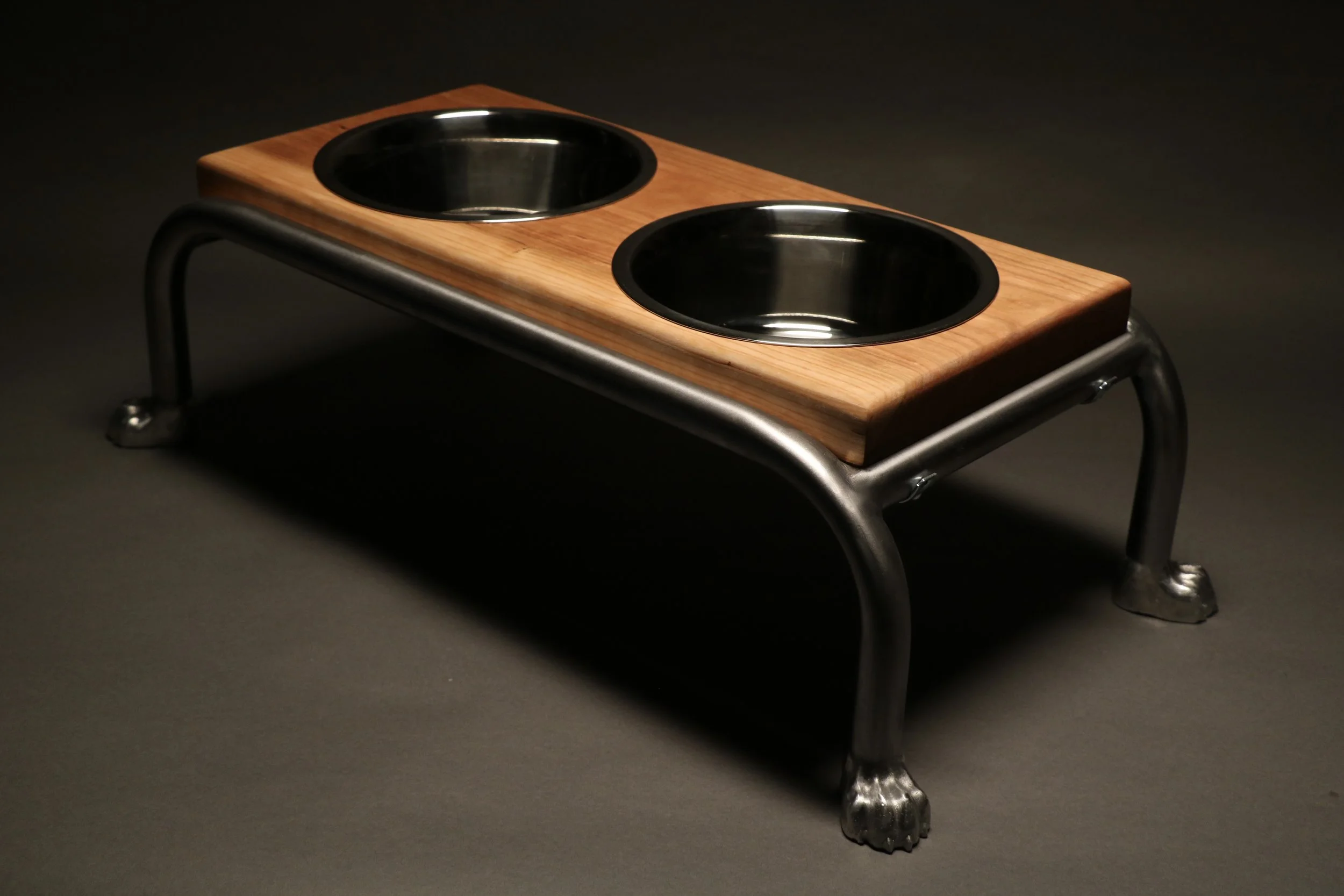
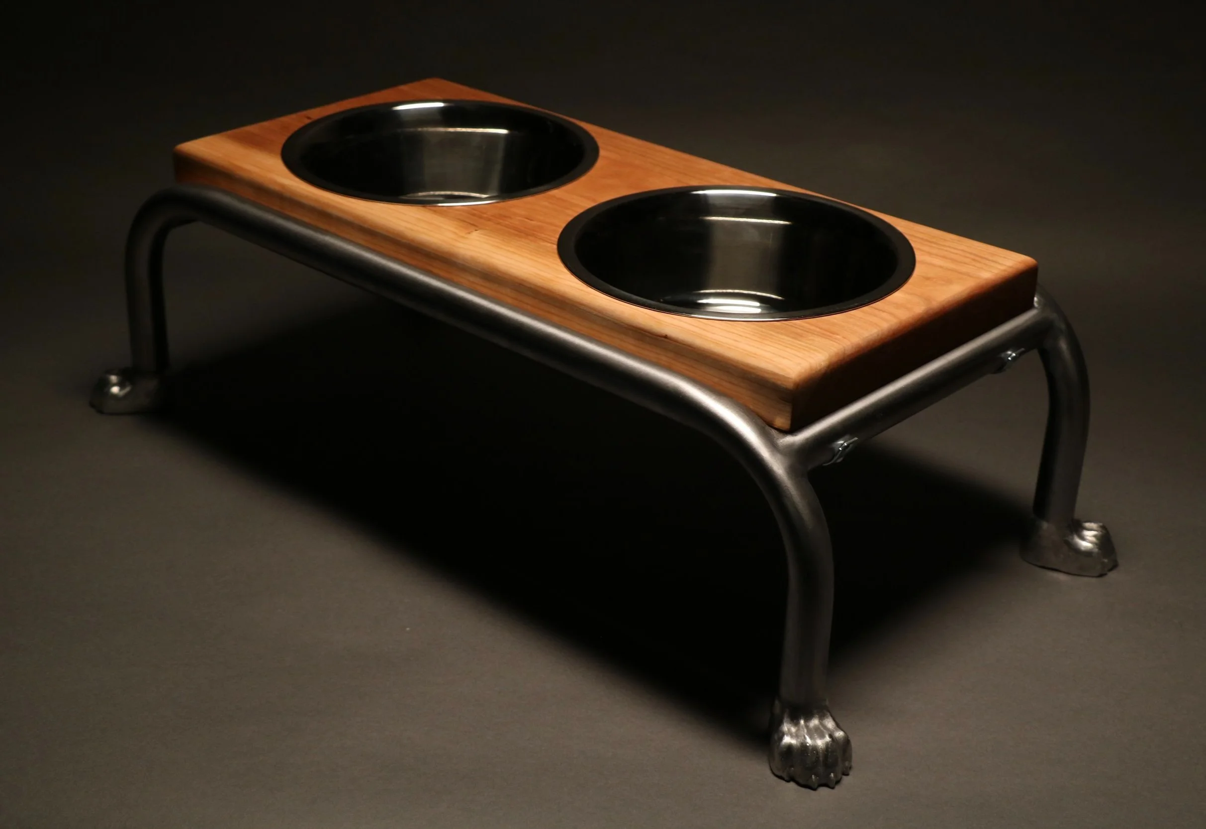
An elegant, elevated feeding station that holds my dog’s food & water bowls
Lyra’s Lunchbox
Materials:
Welded steel tubing
356 Aluminum
Cherry wood
Steel rods
8-32 steel threaded rods
3/4" steel tube clamps
#14 steel phillips flathead screws
Inspiration:
Dogs mean a lot to me and have always been an important part of my life. I grew up with dogs at home, and tried to fill that void during college by dog sitting through Rover and volunteering at a local shelter. Over my gap year after high school, I trained sled dogs in Alaska and worked at a dog shelter in Guatemala. Dogs bring me so much joy, it felt meaningful to dedicate a few months to making something for my dog, Lyra (center pic), and for all the dogs I’ll have in the future.

Sketching:
I sketched all my ideas before I landed on the dog feeding station. Here is my initial quick sketch for the design of Lyra’s lunchbox (which looks absolutely nothing like the final product):

Here is my next set of sketches, after more brainstorming and scoping. I changed the design completely, simplifying the metal tube structure and adding a wooden platform to hold the bowls + dog paws for the feet of the stand!


I also sketched isometric diagrams to help me visualize the structure of the stand:


I prototyped each part many times, as I describe below in my process overview, but first I made two rapid prototypes of the overall structure — one from straws and one from wooden sticks/rods.
Rapid prototyping:
Driver Question: What dimensions should my tube metal dog bowl stand be in order to securely hold the food and water bowls?
For my first prototype, I used straws, which I carefully slotted (and taped) together to form a stand. However, after making it, it looked super small, and I realized I had gotten the wrong dimensions for the dog bowls online.

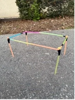

I decided to make my next version out of sturdier materials, so I used wooden sticks/rods and hot glue (and some tape) to form a larger stand that would fit the correct bowl size.
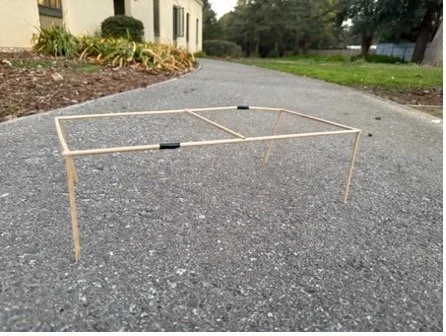

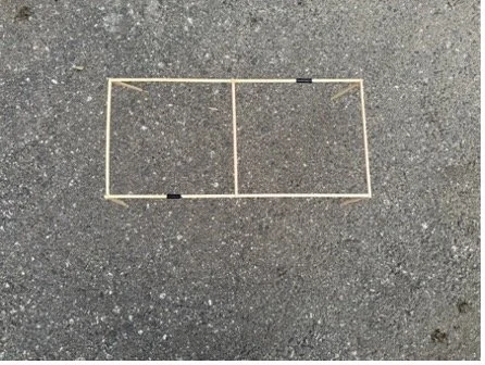
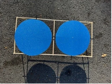
To test my prototype, I made makeshift “bowls” for a size reference by carefully measuring and cutting circles out of thick paper to match the bowl’s diameter. Then I attached thin stirring straws to stick out from the edges of the circles to model the dog bowl rims, which will rest on my structure to support the bowls.

I tested my prototype by placing the makeshift bowls on top of the stand. The bowls didn’t fit perfectly, because I wasn’t able to draw perfect circles, but the test did make me realize that I need more space between the bowls to account for the overlapping lips, which I had forgotten in my measurements. My prototype had a separator between the two bowl slots – which either needs to be thicker, or there need to be multiple separators in the center of the stand.

My testing led to the following questions:
How will I achieve proper separation between the bowls?
How many tubes will I need?
How will I make the base more stable in a fun/aesthetic way?
* question 3 led to the idea for the paws!
Assembly plan:
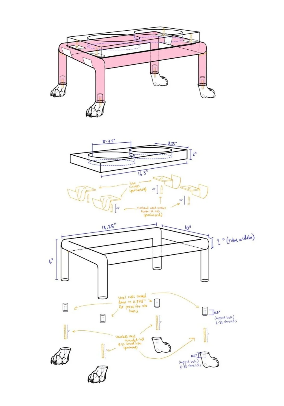
Wooden platform with slots for the food & water bowls
Tube clamps secure wooden platform to the steel tube structure
4 steel tubes, bent and welded together
Steel cylinders press fit into tubes
Cast aluminum dog paws, screwed into steel cylinders
I made cast aluminum dog paws to add a unique, whimsical element to my design — like a vintage bathtub with claw feet.
The first challenge was CAD — I started by sculpting the paw shape from scratch in Blender, using my drawings as a reference:

Process 1: Sand casting

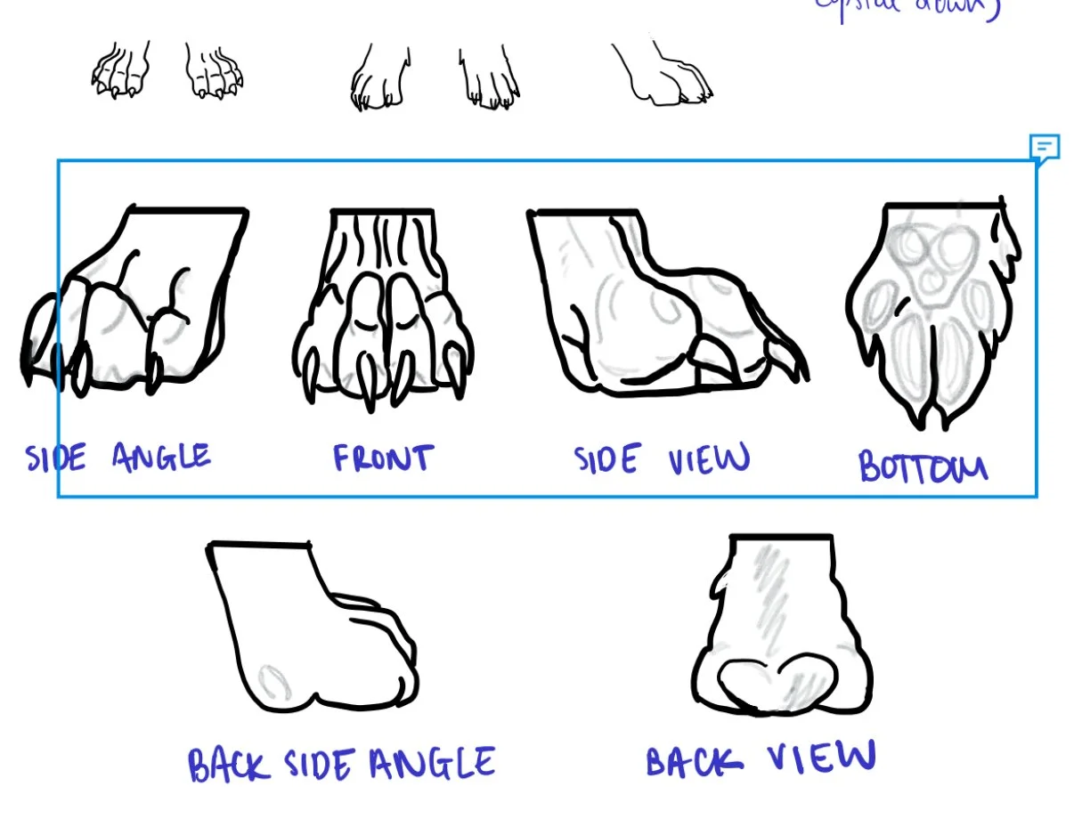
Paw sketches (left), sculpting the paw in Blender (right)

Initial paw model, made in Blender
I then moved the paw into Fusion360 to slice, hollow out, create exact dimensions & uniform thickness, and ensure proper draft angles for casting.

I 3D printed my final model and then hand carved a wooden gate & runner system to form my pattern for casting.

Hollow & drafted paw model in Fusion360 (top), paw model with follow block (bottom)
3D printing my paws & follow blocks for casting pattern (left), Sand casting setup: two paws with a gate and runner between them (right)
It took many attempts to sand cast my paws. The shape was complex, and I had issues pulling my pattern out of the sand. I made a follow block to preserve the undercuts in my design, but the follow block kept sticking to the paws and getting stuck as I tried to pull it out. After many iterations and attempts, I finally had four decent cast aluminum paws.

Process 2: Tube bending
My original design sketches aimed to minimize the number of tubes required for the structure, so I planned to use 4 tubes, bent in different ways. Here are those initial sketches (color coded to represent the 4 tube sections):
I used tube bending to create the legs/structure of my stand, using 1 inch hollow steel tubing.
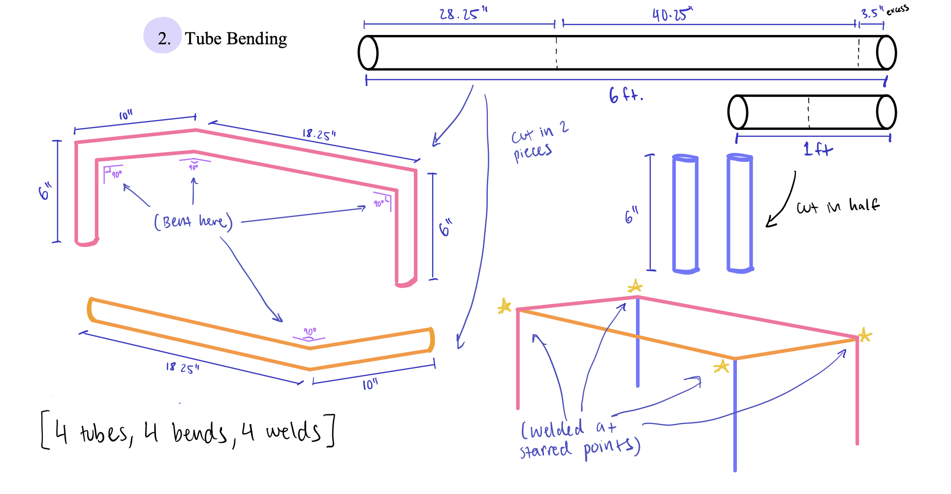

I prototyped my most complex bend (the pink one) early on, to see how accurately I could make the three 90 degree angles:
Takeaway #1: My bends were not perfectly 90 degrees, so I realized I was going to need to make some sort of plate to clamp onto the tube bending machine to stop my part at 90 degrees for greater bend accuracy.


Takeaway #2: I held a small tube section against the top corner of this bend (pictured) and realized that my surface would be uneven if I made the tube sections asymmetrical, because of the different bend geometries at each weld point (which I realized by quickly sketching the bend joints — also pictured).
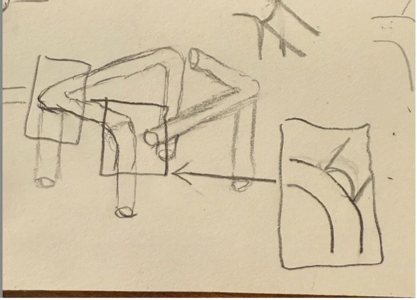

Image & quick sketch of the problem area: this bend joint
This inspired me to completely rethink my design, scrapping the complex bend geometry and changing to a simpler layout of two u-shaped tubes connected by straight tubes. Here is the quick sketch I made of my two new options:

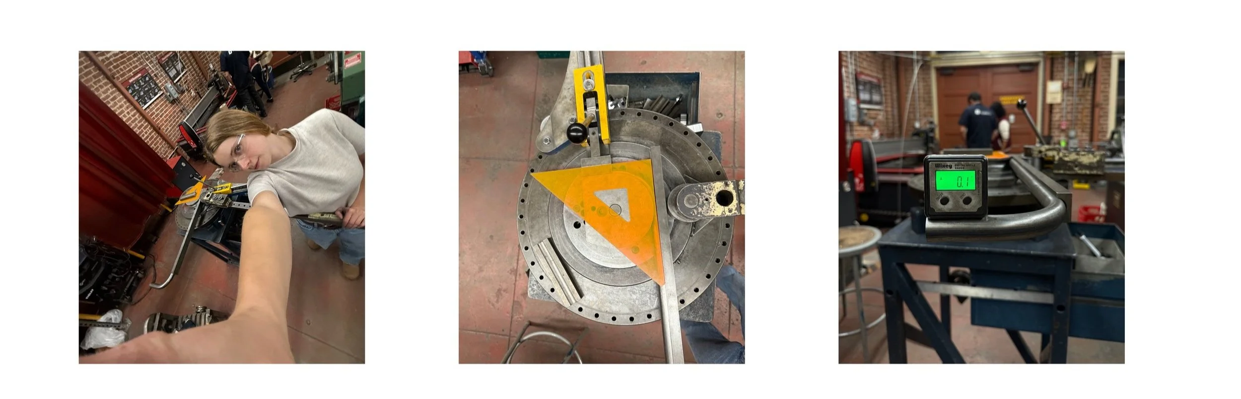
After transitioning to the u-shaped model, tube bending was a relatively painless process. It took a few practice tries to nail the right angles and ensure that I was bending the two legs/shorter sections of the Us on the same plane. I ended up using a level to set it up (pictured below).
Me, tube bending (a great workout!)
Trying to get a perfect right angle bend
Leveling to bend on the same plane
However, I didn’t properly account for the bend radius in my calculations, which messed up my final measurements for the structure and affected my wooden platform, so I had to change some things later on to make it work (I’ll come back to this).

Process 3: Welding
Step 1: I used an end mill to cut fishmouths into the edges of my tubes (bottom left pic)
Step 2: I practiced welding on smaller tube sections, creating mini right angle bend joints to imitate my actual weld constructions (bottom center pic). I attempted five oxy-acetylene welds and blew holes in almost every one before I decided to try TIG welding instead.
Step 3: I spent another few days learning to TIG weld and practicing on smaller tube joints. When the time came to weld my actual part, I felt very confident in my TIG welding abilities. I completed my first two welds beautifully and was very proud of myself (bottom right pic).

Fishmouthing tubes on the mill
Practice welds on mini tube joints
TIG welding the first two joints
However, the next two welds were a lot harder. First, I had to do crazy setups to clamp the whole stand together and try to angle it so I could reach my weld joints (some of these crazy setups pictured below).
Also, at this point our lab’s TIG weld was being super wonky and nobody could figure out why. The electricity was sputtering around at the start of each arc. At this point I was all set up, and there was no other option, so I did it anyway… and made some very messy, ugly welds. That meant… a lot more finishing!

Step 1: I used the lathe to turn down short steel rods until they were the right size to press fit into my tubes (which I tested a few times, starting with 3 thou larger than the hole, to find the perfect size).
Step 2: I drilled and tapped the steel rods and the tops of my paws (which I secured carefully on the mill using strap clamps) and screwed the rods into the paws with 8-32 threaded rods.

Attaching paws to tubes
Step 3: I press fit my paws (with rods attached) into the tube legs. This was difficult, because I had tested my press fits on smaller sections of tubes, but when I tried to press fit the rods into the tube legs of the larger structure forming my stand, it was much harder to orient the stand in the press (because it was so big and bulky). I ended up using a hammer to press them in, which worked, but rotated the paws slightly as they went in (so they weren’t oriented the way I wanted them). To fix this issue, I used thread locker to lock the paws in the orientation I wanted.


Sketches mapping out my paw attachment plan
Step 1: Turning cylinders for press fit
Step 2: Drilling & tapping rods & paws
Step 3: Press fitting rods & paws into tubes
As I mentioned in the tube bending section, I mis-estimated the tube bend radii (and also my welds weren’t perfectly straight), so it was up to the wooden platform, my final step, to even it all out.

Woodworking
Step 1: I cut a piece of paper to figure out the exact dimensions I would need for the wood to slot down between the long sides of my tube structure and rest on onto the lower, shorter sides (left pic).
The first piece I bought was too small (right pic), because the measurements had all changed due to my bend radius miscalculation, so I sold it and bought a new one.


Sizing my platform with paper
Measuring my wood (too small)
Step 2: I used a saw to cut my new wood piece to size.
Step 3: I cut circles out of my wood for the bowls to slot into, which was not easy. I laser cut a hole template to guide the router, but it was super slow, so I tried a bunch of other methods. I ended up using a jigsaw to hand cut out a rough shape, and then finished them off with the router (guided by my template). Like everything else, this took much longer than expected.

Buying my wood
Cutting my wood to size
Laser cutting circle templates
Setting up my templates to cut holes
Finishing
To finish, I angle grinded my messy welds to make the joints look smooth and perfect, and then wire brushed the whole tubing structure. I chose a wire brush finish because I like how it looks smooth and semi-matte. Also, the slightly lighter metallic color of the wire brushed steel matches better with the color of the aluminum paws.
I sanded and oiled my wood to bring out its natural cherry color, which matches my kitchen at home. Then I attached the wood to the tube structure with tube clamps.

angle grinding welds
I filed, grinded, and sanded my paws over the course of a few weeks. I was not striving for a mirror finish or a very high grit, just a natural, even, sanded cast finish. I wanted it to be clear that these parts are sand cast, and I think the slight impurities look cool – after all, dog paws are natural and imperfect forms.
wire brushing tubes
oiling wood (& screwing it on with tube clamps)

Cast paws: filing, belt sanding, grinding, hand sanding